3.3.2. Predicted Data File

Predicted data files are output by the code dcipoctree_fwd.exe. If DC data are being simulated, then a data_dc.txt file is output. If IP data are being simulated, then both a data_dc.txt and data_ip.txt file are output. The format of these files are the same, except for the data columns.

The general format for predicted data files is shown below.

Note

The [ ] brackets are used for columns are not always required. For example, the Z value for surface data with flat topography.


\(\;\;\;X_A(1) \;\;\;\;\;\;\;\;\; Y_A(1) \;\;\;\;\;\;\;\;\, [Z_A(1)] \;\;\;\;\;\;\;\; X_B(1) \;\;\;\;\;\;\;\; Y_B(1) \;\;\;\;\;\;\;\;\; [Z_B(1)] \;\;\;\;\;\;\;\;\;\;\; N\)
\(\;X_M(1,1) \;\;\;\; Y_M(1,1) \;\;\;\;\, [Z_M(1,1)] \;\;\;\;\, X_N(1,1) \;\;\;\;\, Y_N(1,1) \;\;\;\;\, [Z_N(1,1)] \;\;\;\; DATA(1,1)\)
\(\;X_M(1,2) \;\;\;\; Y_M(1,2) \;\;\;\;\, [Z_M(1,2)] \;\;\;\;\, X_N(1,2) \;\;\;\;\, Y_N(1,2) \;\;\;\;\, [Z_N(1,2)] \;\;\;\; DATA(1,2)\)
\(\;X_M(1,3) \;\;\;\; Y_M(1,3) \;\;\;\;\, [Z_M(1,3)] \;\;\;\;\, X_N(1,3) \;\;\;\;\, Y_N(1,3) \;\;\;\;\, [Z_N(1,3)] \;\;\;\; DATA(1,3)\)
\(\;\;\;\;\;\;\;\;\;\vdots\;\;\;\;\;\;\;\;\;\;\;\;\;\;\;\vdots\;\;\;\;\;\;\;\;\;\;\;\;\;\;\;\;\;\;\vdots\;\;\;\;\;\;\;\;\;\;\;\;\;\;\;\;\;\;\;\vdots\;\;\;\;\;\;\;\;\;\;\;\;\;\;\;\;\;\vdots\;\;\;\;\;\;\;\;\;\;\;\;\;\;\;\;\;\vdots\;\;\;\;\;\;\;\;\;\;\;\;\;\;\;\;\;\;\;\vdots\)
\(X_M(1,N) \;\;\; Y_M(1,N) \;\;\; [Z_M(1,N)] \;\;\; X_N(1,N) \;\;\; Y_N(1,N) \;\;\; [Z_N(1,N)] \;\;\; DATA(1,N)\)

\(\;\;\;X_A(2) \;\;\;\;\;\;\;\;\; Y_A(2) \;\;\;\;\;\;\;\;\, [Z_A(2)] \;\;\;\;\;\;\;\; X_B(2) \;\;\;\;\;\;\;\; Y_B(2) \;\;\;\;\;\;\;\;\; [Z_B(2)] \;\;\;\;\;\;\;\;\;\;\; N\)
\(\;X_M(2,2) \;\;\;\; Y_M(2,2) \;\;\;\;\, [Z_M(2,2)] \;\;\;\;\, X_N(2,2) \;\;\;\;\, Y_N(2,2) \;\;\;\;\, [Z_N(2,2)] \;\;\;\; DATA(2,2)\)
\(\;X_M(2,1) \;\;\;\; Y_M(2,1) \;\;\;\;\, [Z_M(2,1)] \;\;\;\;\, X_N(2,1) \;\;\;\;\, Y_N(2,1) \;\;\;\;\, [Z_N(2,1)] \;\;\;\; DATA(2,1)\)
\(\;X_M(2,3) \;\;\;\; Y_M(2,3) \;\;\;\;\, [Z_M(2,3)] \;\;\;\;\, X_N(2,3) \;\;\;\;\, Y_N(2,3) \;\;\;\;\, [Z_N(2,3)] \;\;\;\; DATA(2,3)\)
\(\;\;\;\;\;\;\;\;\;\vdots\;\;\;\;\;\;\;\;\;\;\;\;\;\;\;\vdots\;\;\;\;\;\;\;\;\;\;\;\;\;\;\;\;\;\;\vdots\;\;\;\;\;\;\;\;\;\;\;\;\;\;\;\;\;\;\;\vdots\;\;\;\;\;\;\;\;\;\;\;\;\;\;\;\;\;\vdots\;\;\;\;\;\;\;\;\;\;\;\;\;\;\;\;\;\vdots\;\;\;\;\;\;\;\;\;\;\;\;\;\;\;\;\;\;\;\vdots\)
\(X_M(2,N) \;\;\; Y_M(2,N) \;\;\; [Z_M(2,N)] \;\;\; X_N(2,N) \;\;\; Y_N(2,N) \;\;\; [Z_N(2,N)] \;\;\; DATA(2,N)\)

\(\;\;\;\;\;\;\;\;\;\vdots\;\;\;\;\;\;\;\;\;\;\;\;\;\;\;\vdots\;\;\;\;\;\;\;\;\;\;\;\;\;\;\;\;\;\;\vdots\;\;\;\;\;\;\;\;\;\;\;\;\;\;\;\;\;\;\;\vdots\;\;\;\;\;\;\;\;\;\;\;\;\;\;\;\;\;\vdots\;\;\;\;\;\;\;\;\;\;\;\;\;\;\;\;\;\vdots\;\;\;\;\;\;\;\;\;\;\;\;\;\;\;\;\;\;\;\vdots\)

where

  • \(X_A(i) \;\;\; Y_A(i) \;\;\; [Z_A(i)]\) is the Easting, Northing and vertical (if needed) position of the A-electrode for source \(i\).

  • \(X_B(i) \;\;\; Y_B(i) \;\;\; [Z_B(i)]\) is the Easting, Northing and vertical (if needed) position of the B-electrode for source \(i\).

  • \(X_M(i,j) \;\;\; Y_M(i,j) \;\;\; [Z_M(i,j)]\) is the Easting, Northing and vertical (if needed) position of M-electrode associated with source \(i\) and receiver \(j\).

  • \(X_N(i,j) \;\;\; Y_N(i,j) \;\;\; [Z_N(i,j)]\) is the Easting, Northing and vertical (if needed) position of N-electrode associated with source \(i\) and receiver \(j\).

  • \(DATA(i,j)\) is the datum associated with the \(i^{th}\) source and \(j^{th}\) receiver.

    • For DC data, \(DATA(i,j)\) represents a normalized voltage value followed by an apparent resistivity value.

    • For IP data, \(DATA(i,j)\) represents the IP data value defined in the input file (see line 1).

3.3.2.1. Example 1: Dipole-Dipole Surface Data

For electrodes defined only on the surface, the vertical location is determined by the topography. As a result, columns for the vertical position of each electrode are not required. Below, we see the format for data_dc.txt and data_ip.txt. In this case, there are two sources, each with a different number of receivers.

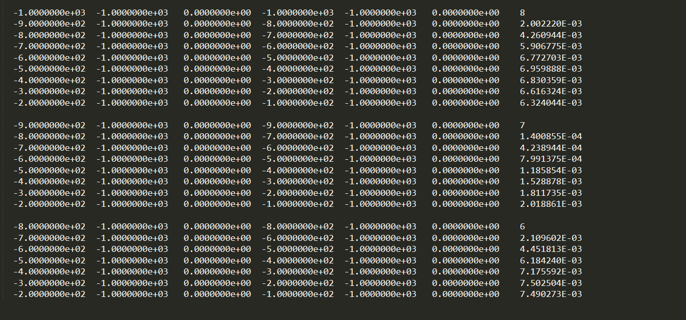
Predicted Surface DC Data

../../_images/dpred_dipole_dipole_XY_dc.PNG

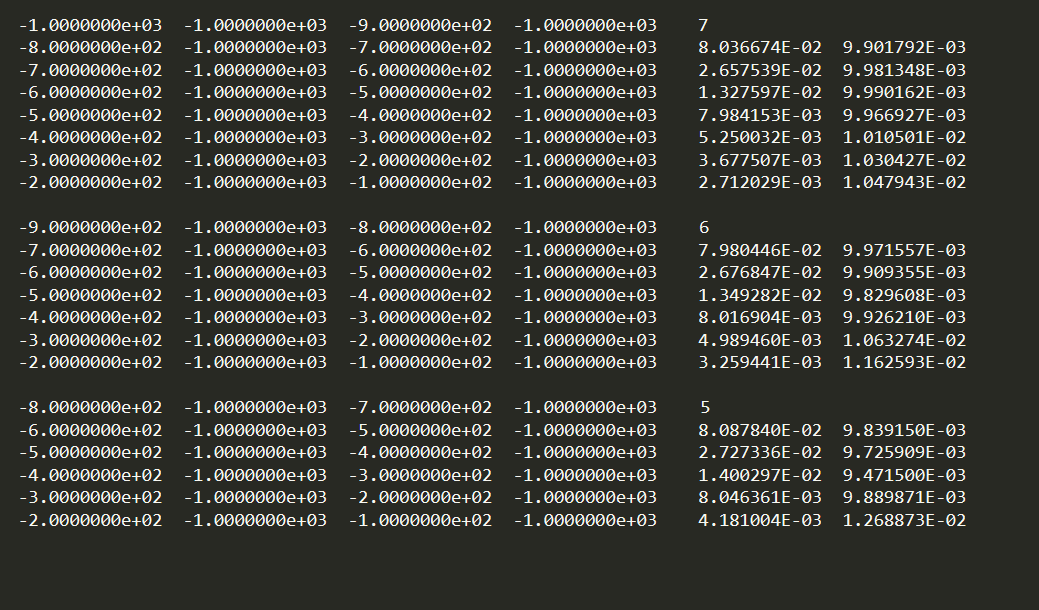
Predicted Surface IP Data

../../_images/dpred_dipole_dipole_XY_ip.PNG

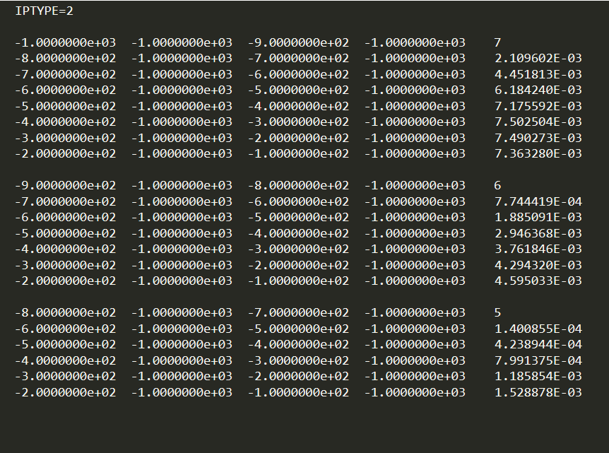
3.3.2.2. Example 2: Pole-Dipole Data with General Format

For the general data format (surface and/or borehole), the vertical locations of the electrodes are defined. Below, we see the format for data_dc.txt and data_ip.txt. Since the sources are pole sources, we see that the locations of the A and B electrodes are identical. If the receivers were poles, the M and N locations of corresponding M and N electrodes would be identical.

General Format Predicted DC Data

../../_images/dpred_pole_dipole_XYZ_dc.PNG

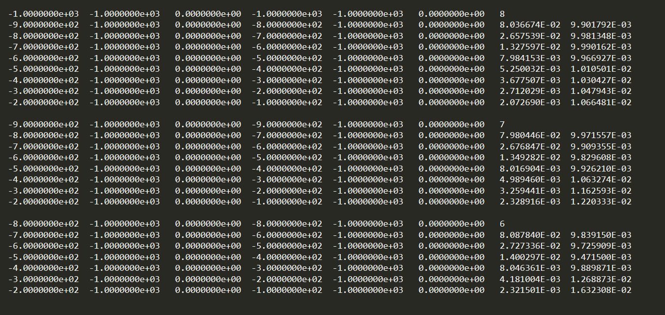
General Format Predicted IP Data

../../_images/dpred_pole_dipole_XYZ_ip.PNG